ISA-to-I2C Interface

The ISA-to-I2C Interface Card allows systems to access peripherals on an I2C bus. The card is based around the PCF8584 IC, and can operate at a frequency of up to 90 kHz when operating as the I2C bus controller. While the PCF8584 is an older part, it integrates better with the 5V-centric ISA bus. The card uses hand-solderable through-hole components for all components except the PCF8584 chip, which is surface-mount to reduce the overall cost of the card.
The card can be used to add additional functionality to a system without consuming ISA card slots. For example, you could add a real-time clock, temperature sensor, and EEPROM, all for the cost of a single ISA card slot.
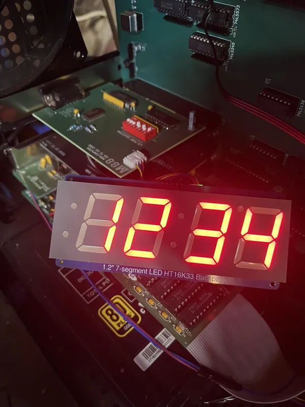
To simplify connectivity to external I2C devices, STEMMA connectors are used. These provide +5V and GND, in addition to the I2C SDA and SCL signals. A great deal of external modules
are available that can be connected through these connectors.
Purchase
These cards are going through final testing and will be available for purchase soon at the M88 Tindie store.
Quick Start Guide
Check out the Quick Start Guide that is included with every shipped card.
Programming Examples
The I/O port address for programming is configured with a DIP-Switch on the card. This allows you to set the base address of the card to avoid conflicts with other peripherals that you may have installed in your system.
Initialization
-
Write
80htoPORT+1. This disables the I2C bus, and selects register S1 for writing. -
Write
55htoPORT. This writes the controller's own address (AAh) to the S1 register. You can choose the I2C address by modifying this value; it is the address shifted right one bit. -
Write
A0htoPORT+1. This selects register S2 for writing. -
Write
10htoPORT. This configures the S2 clock register for 90 kHz operation with a system clock of 4.43 MHz. Refer to the PCF8584 datasheet for other values to use for faster system clocks. -
Write
C1htoPORT+1. This enables the I2C bus and shifts it into an idle state.
Sending Data
-
Wait for the bus to become idle by polling
PORT+1until bit 1 (bus busy, active low) is set. -
Write the target address to
PORT, shifted right by one bit. Set bit 8 to 0 ("write"). -
Write
C5htoPORT+1, which generates the I2CSTARTand emits the target address. -
Poll the S1 register by reading
PORT+1until bit 8 (status) is clear. - Check that bit 4 (LRB) is clear - if it is not, the target did not acknowledge, and further transmission should be skipped, so jump to 8.
- If all data bytes have been sent, jump to 8.
- Write a data byte to
PORT. Loop back to 4. -
Write
C3htoPORT+1. This transmits the I2CSTOPand ends the transaction.